|
Willkommen,
Gast
|
|
USS NAUTILUS, PART-3
Unlike most other wet-hull type r/c submarines, this one -- because of the need to achieve an unbroken linkage to the SubDriver (WTC), located in the lower hull, and the bow plan operating and retract linkages, also located in the lower hull -- features a U-cut type break between the two hull halves. With the U-cut both radial breaks occur from centerline up to the top of the hull. Unfortunately, the U-cut prevents tilting of the upper hull as it's placed down on the lower hull. Where the more familiar Z-cut, with its high radial cut aft and low radial cut forward permits use of a radial capture flange forward, and a single machine screw aft to secure the entire hull assembly -- an assembly that requires angling in the two hull halves during assembly. Not so with a model. making use of right- angle U-cuts. Presented here is how I worked out the fasteners used to hold the two hull halves together, as well as how 'indexing bolts' (as the German's would describe them) are employed to index the two hull halves tightly together against transverse loads. 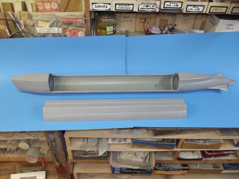
With this type hull separation scheme some means of registering the two hull halves together has to be devised so that they fit together as a tight, non-shifting unit, secured with the minimum number of mechanical fasteners. I worked out an array of indexting pin-in-hole bolts along the longitudinal flanges of the upper and lower hull pieces to prevent transverse motion of the assembly. I would love to claim authorship to this feature, but .... ... It's a system I stole from Andreas (who produces this kit). He chronicled the use of the pin-in-hole indexing array in this excellent U-1 WIP thread, www.modelboatmayhem.co.uk/forum/index.ph...SESSID=a645ffa44d710 9f83a6a4d50934dcc7b Longitudinal regidity and alaignment was assured by the vertical flanges at the radial edges of the upper and lower hull. Closure was achieved by a fore and aft machine screw holding the upper hull down upon the lower hull - - that required manufacture and installment of two brass foundation pieces to receive those screws. 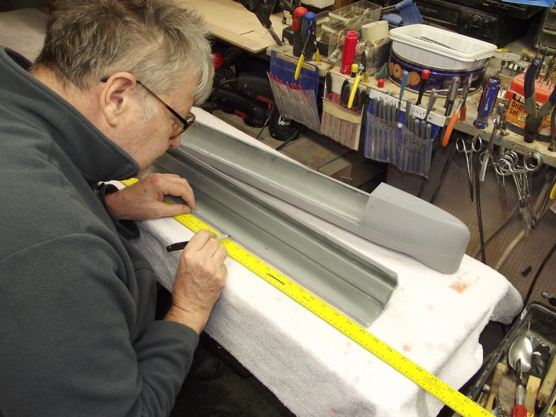
The pin-and-hole indexing array, that would register the longitudinal edges of the upper and lower hull halves together, started by working out an even spacing between the pins and holes along the length of the flanges. This done with Sharpie-pen and ruler. [img]http://i68.servimg.com/u/f68/18/50/47/55/d scf9011.jpg[/img] The pin-and-hole indexing array started with laying out of longitudinal lines. That job best done with a compass: the pen point set high enough to cause the shank of the compass needle to ride along the outer face of the hull as the tool is drawn along, its pen tip inking a line along the length of the flange face. I elected to install the pins within the flanges of the upper hull half, and the holes to receive the points of those pins drilled into the lower hulls longitudinal flanges. [img]http://i68.servimg.com/u/f68/18/50/47/55/d scf9024.jpg[/img] The compass was adjusted to put the inked line in the center of the flange. As the tool retained its initial setting during the mark-off of the four longitudinal flanges, I was assured uniformity of line-to -hull- surface spacing. close enough for government work. However, as a check, I would later use an old pattern-makers trick to assure a more precise mark-off to assure proper alignment of pin-to-hole. 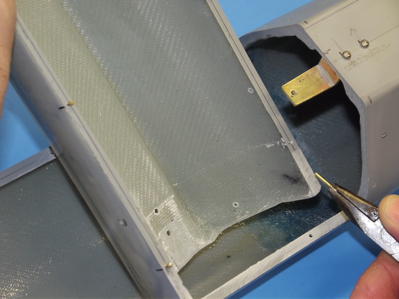
The trick is to work one pin-hole pair at a time. Not till a set of pin and hole had been successful achieved, would I move on to the next set. The process: First, I drill a 1/16" hole into one of the marked spots along the longitudinal flange of the upper hull. A short length of 1/16" diameter brass rod is chucked up into a moto-tool and spun as I filed one end to a blunt point. The pin was then inserted into the hole, pointy end of the pin projecting over the flange face by 3/32". The next step is to accurately mark onto the lower hull longitudinal flange where the center of this pin goes. 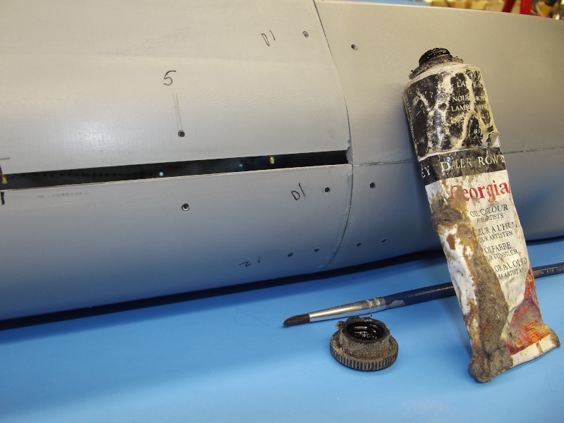
I applied a very, very small amount of oil paint (black) to the tip of the friction fit pin, then carefully placed the upper hull down onto the lower hull. I kept pushing till the pin makes contact with the lower hulls longitudinal flange -- and kept pushing till the pin was pushed back with its tip flush with the upper hulls flange face. Removing the upper hull revealed a small dot of paint on the lower hulls longitudinal flange where I would drill a hole to pass the pin. That hole slightly larger than 1/16" (.062") -- this to provide a non-interference fit between pin and hole. That bit was a .064" drill. This produces a very tight, non-interference fit between pin and hole. After removing the upper hull, the pin is pushed to project it's tip 3/32" past the plane of the flange, and CA applied to the inboard side of the flange to affix the pin in place. The two hull halves were assembled to insure a correct fit, then separated and I moved on to the next pin-hole combination. the cycle repeated till the job done. 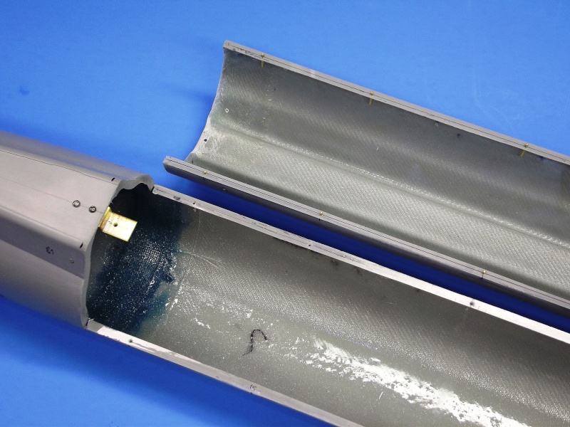
The completed pin-in-hole array seen along the longitudinal flanges of the upper and lower hull halves. The forward screw foundation. Manufactured from 1/2" wide, 3/32" thick brass strip, and bend to a 'Z' shape, is seen here temporarily held within the forward section of lower hull with two 2-56 X 1/4" long machine screws -- these screws eventually removed to clear the way for installation of the eventual forward acid-etched deck piece. 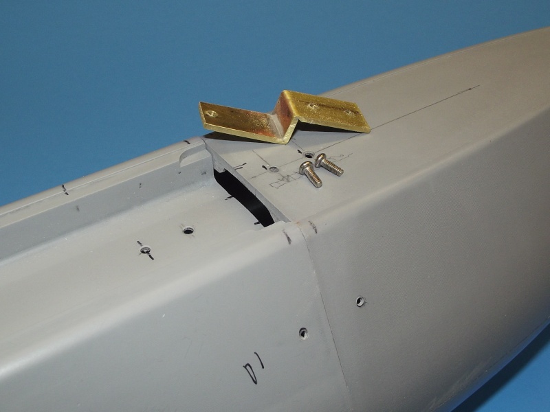
Two hull closure machine screws, one forward the other aft, eventually secure the upper hull to the lower hull. The two foundations (the forward one seen here) becoming the interface fixtures between the two halves. (Note the second hole, aft of the other, in the trough of the upper hull. The initial intent was to employ a longer foundation tongue, but that was found to put too much strain on the right-angle bend at the bottom of the foundation piece. With the shorter moment the assembly became a bit more ridged). 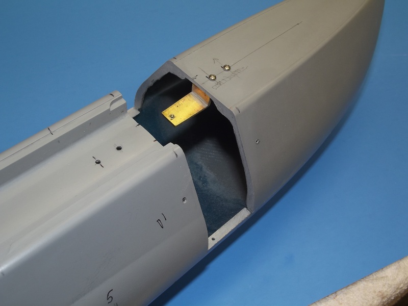
Temporarily attached to the forward portion of lower hull, the forward screw foundation is seen with the upper hull not yet positioned in place. You can see how a securing machine screw would pass through the hole in the trough of the upper hull, pulling it down and onto the foundation, holding the hull halves in place. 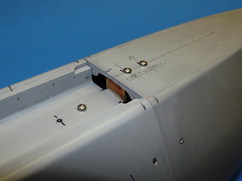
This is the end-game: A solid, ridged foundation upon which the inboard side of the upper hull rests upon. So arranged the upper surfaces of the hull halves match perfectly. So, with the pin-in-hole array I've forced the longitudinal union between the two hull halves to index tightly against transverse loads; and the two foundations with securing screws pulling the upper hull half down upon the lower hull half. 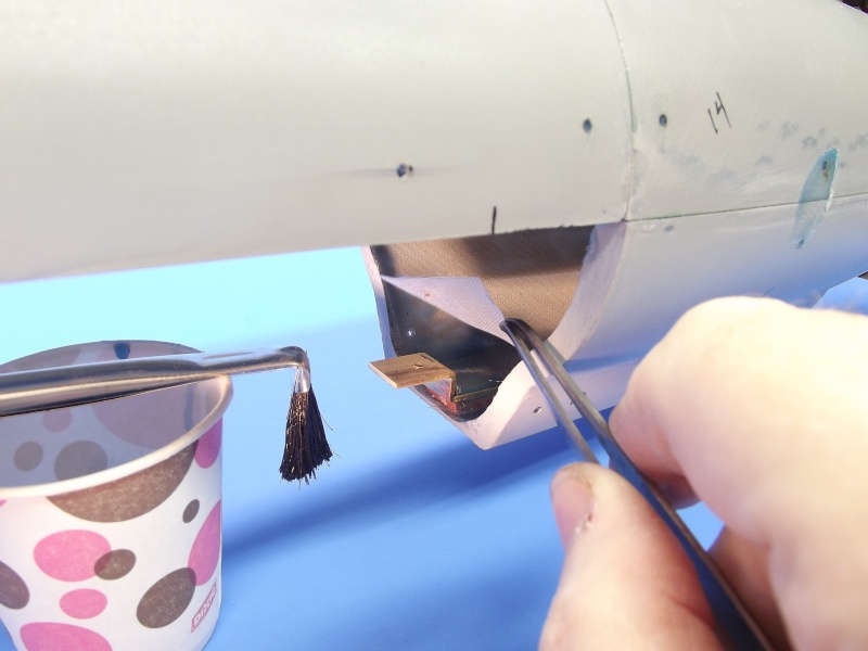
The upper hull was removed, the lower hull inverted, and CA applied to the foundation-hull matting surfaces, and when cured hard, the temporary securing screws were removed. Then some laminating resin was catalyzed and reinforcing strips of two-ounce glass cloth laid in to strengthen the foundation bonds. |
|
Bitte Anmelden um der Konversation beizutreten. |
|
NAUTILUS PART-4
In this part I'm concentrating on how to handle, cut, and trial position the two acid-etched deck pieces. As I departed from the radial aft break to the hull -- this kit designed as a dry-hull with a single radial break aft employing a watertight bayonet type closure. However, I opted for a wet-hull arrangement which, as the hull kit parts were arranged required two radial backs atop the hull. This change meaning I had to split the forward acid-etched deck piece into two pieces in order to work over the forward radial break. In addition to outlining the care and feeding of this kits acid-etched deck pieces, I'll also give you some insight into just what the acid-etching process -- more correctly described as, chemical machining -- entails to give you a better idea of the end-products strengths and weaknesses. 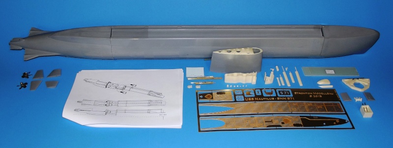
THIS is one complete kit: detailed illustrated orthographic and isometric drawings; two beautiful cast brass propellers; GRP sheet marked off to indicate where to cut; bubble free perfectly symmetrical and tight fitting resin pieces; and a complete set of acid-etched parts for the deck, sail bridge, radar reflector, and even a painting stencil used to spray-brush on the large white '571' that goes on each side of the sail. 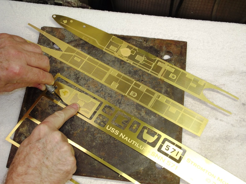
First step is to part the two deck pieces from the tabs that connect them to the fret. This best done with a sharp knife pressing down onto a firm, un-giving surfaces -- such as a sheet of glass or, in this case, a slab of sheet iron. Place the blade edge perpendicular to the work, where the tab meets the part, and press down firmly. 'Snap'! As the part is cut free of the frets tab. 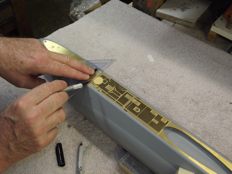
To insure I made the initial forward brass deck cut exactly over the radial seam at the bow, I laid in the two acid-etched deck pieces -- which indexed perfectly within the shallow trenches of the hull there to fit them flush with the top of the hull -- and only then laid down a straight-edge and made the first light passes with a brand new #11 blade. The forward acid-etched deck piece was removed from the hull, placed on the cutting plate and at least ten light passes of the knife made, using the initial cuts to guide the blade. The piece was flipped and a straight-edge used to guide the blade as that side was scored. 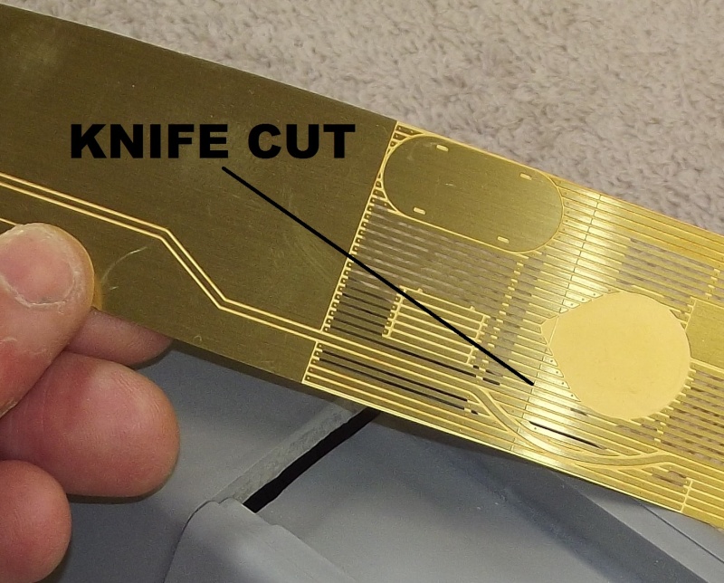
The acid-etched deck pieces are chemically cut from brass sheet. This is flimsy stuff as it is, but after eating away a substantial portion of the material to achieve the high relief and through detailing, the part become exceptionally prone to handling damage. For this reason, other than using a very thin diamond saw, you should refrain from using traditional sawing tools to part one acid-etched part from another. Instead, as I've illustrated here, you make knife cuts along both faces of the piece; sandwich each half between hard-wood strongbacks; and slightly flex, back-and-forth, the parts at the knife cut till the metal fractures. 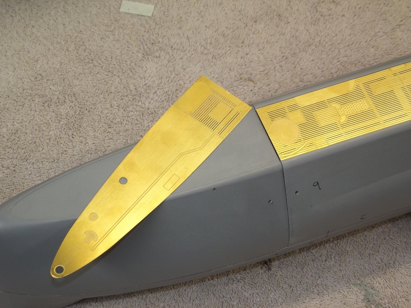
In this shot, you can make out the slight recess in the bow that permits the face of the deck piece to mount on the same plane as the GRP hulls deck. Incidentally, the seam between acid-etched deck and hull, not by any accident, is the same demarcation line between the real NAUTILUS hull and deck. This is one accurately engineered and detailed model kit! Seen to good advantage here is the break in the forward acid-etched deck piece made to accommodate the forward radial break between upper and lower hull halves. 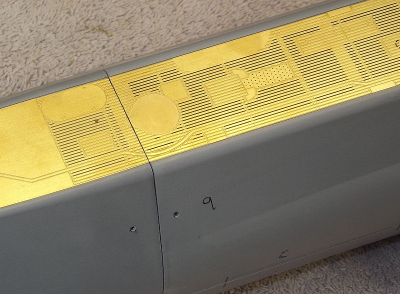
Andreas lavished a great deal of research effort and drawing preparation on his kit. It shows in the highly detailed brass metal deck kit parts. He employed a second-party contractor to produced the acid-etched parts -- that outfit using Andreas' art-work to render the engraved and opened details. The process in professional circles referred to as, two-face 'chemical machining'. Acid-etching to you and me. The process goes something like this: A piece of brass or stainless steel plate is cleaned and both sides coated with an air-dry photo-sensitive resin. the sensitized metal sheet is sandwiched between two indexed negative/positive film masks. The top mask represented those portions of deck that will be cut all the way through as well as those areas that are to be cut half-way through. The bottom mask represents those portions of the deck that have to be cut all the way through. Once the photo-sensitive resin is exposed (typically an intense ultra-violet light), the masks are removed, and the sheet agitated within a developer solution that removes/protects the light activated portions of resin. At this point specific portions of the sheet are protected by the resin, the other portions of metal unprotected and now subject to oxidation. The developed sheet is then subjected to either a hot acid or caustic solution soak/impinging spray. Oxidation or corrosion eats away those areas of sheet no longer protected by the resin coating. Hence the term, 'chemical machining'. And you wind up with the thin metal sheet (the 'fret' in some circles) possessing incredibly defined engraved and open areas. Typically, for economies sake, the fret will contain many different acid-etched model parts and masks -- the items within the fret held in place my tiny tabs, elements of the original art-work. 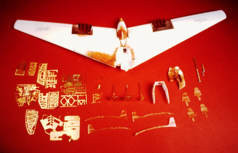
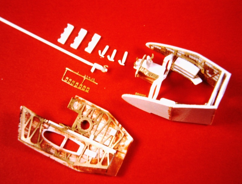
This little scratch-build model demonstrates the correct selection of materials and fabrication process to suit specific tasks: acid-etched brass sheet to form cockpit detail, markings painting masks, l.g. doors; cast resin parts for small parts of compound curves; and vacuformed polystyrene sheet for large, hollow, low- weight structures of compound curves. 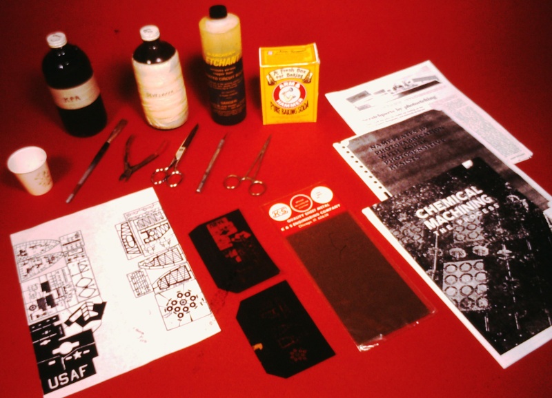
Why do I know so frig'n much about the process of acid-etching? Because I do it myself, in-house. Like all model building techniques this process has its uses. But, only in specific situations. The talent is knowing what fabrication process to employ for specific parts, and when. Acid-etching employed here to achieve incredibly small, well detailed parts and and painting masks. Andreas' kits is an example of correct material and process selection -- each type material and process suited to a specific type part: laid up GRP where you need thin-walled items of high strength and of compound curve; cast metal where thin walled strength and natural color is required; and acid etched items where thin-section plate of fine surface detail is desired. The right material and fabrication process for the right job. 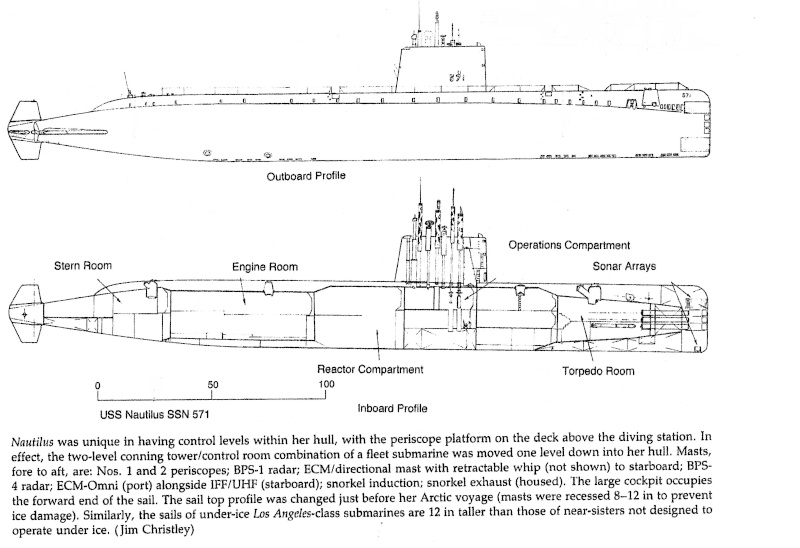
The one mystery as to the NAUTILUS detailing not resolved in the kit is the number, placement, and size of the bottom hull ballast tank flood and drain holes, and main seawater suction and discharge holes. Searching my files I found this excellent Jim Christley drawing showing the as-launched NAUTILUS in profile, both cut-away and external. And it's the upper drawing that revealed a great deal of information on those hull penetrations -- holes I'll have to cut into the lower hull for both scale and functional reasons. |
|
Bitte Anmelden um der Konversation beizutreten. |
|
part-5
Basic hull assembly done, it came time to address the control surface linkages, running gear, and the removable SubDriver (SD, also known as 'water tight cylinder') foundations. I first replaced the kit provided metric sized control surface operating shafts and propeller shafts with slightly smaller units sized to the imperial system. ... Hey, this is America! We don't do no stik'n metric! I also took the opportunity to test fit the sail atop the hull as well as checking the fit of the four acid-etched deck pieces. The primary objective here was to get everything that movies on this model to work correctly from the source, the SD. 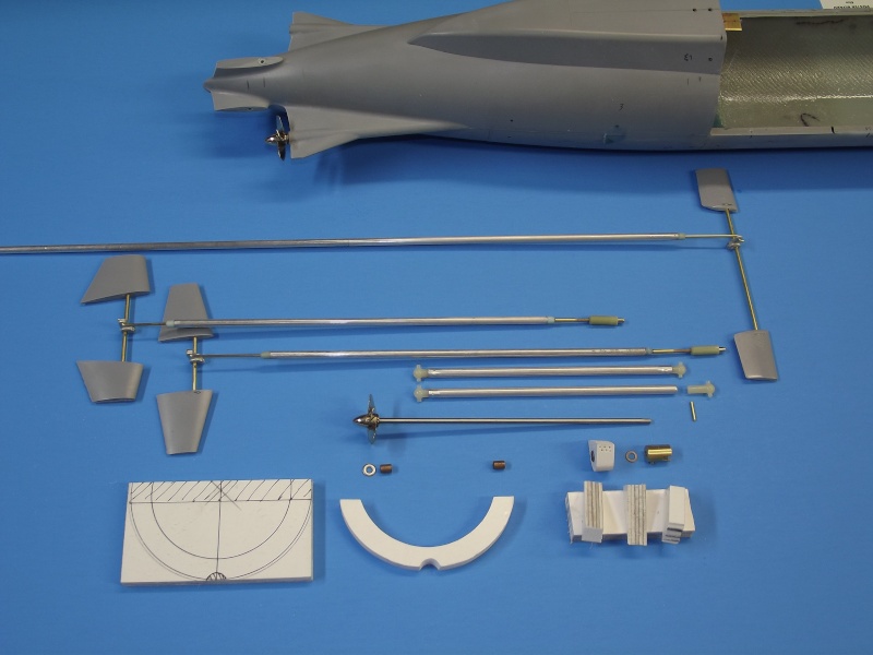
The kit provides all the parts and documentation needed to produce a very credible model of the USS NAUTILUS. However, other than the way the hull parts break down, provision of propeller shafts, control surface operating shafts, and perfectly formed and positioned propeller shaft bores (stern tubes), it's the job of the kit assembler to come up with the hardware and devices required to convert the kit . The control surface linkages, some elements of the running gear, and means of mounting the SD (which contains those control, propulsion, and ballast sub-system elements that must be housed in a dry environment) have to be fabricated or purchased separately by the customer. You see some of that work above in the form of linkages, running gear, and SD mounting hardware. 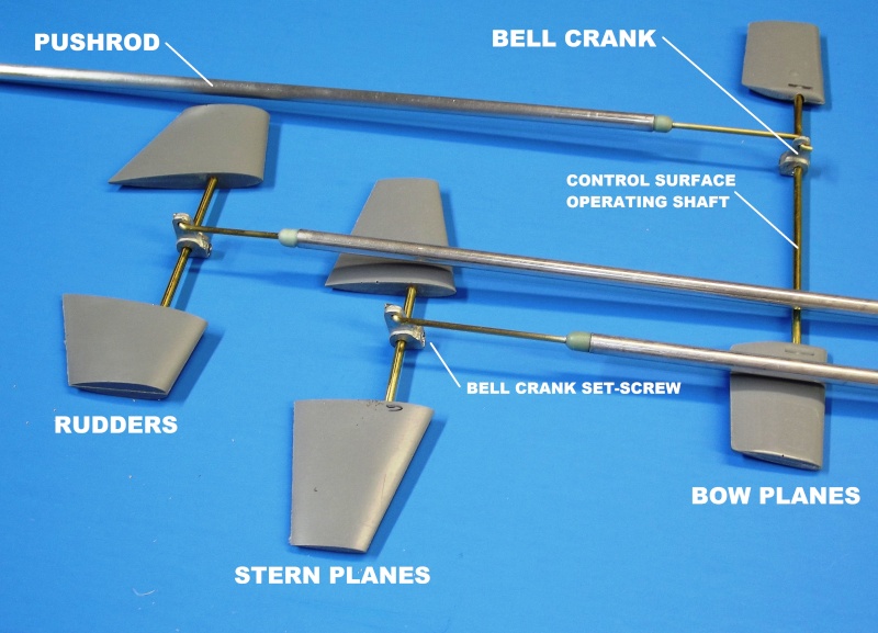
All three sets of control surfaces (stern planes, rudders, and bow planes) are simple affairs: Each set of control surfaces has a straight run-through operating shaft -- there is no need to provide shaft avoidance yokes, which is the case in most single-shaft designs. The two shafts of the NAUTILUS provide plenty of clearance in the stern for straight-through stern plane and rudder operating shafts -- a desirable situation also made possible by the two sets of operating shafts being well distanced longitudinally. The cast white metal bell-cranks were at hand: these are parts of my own manufacture, used in our line of plastic model submarine fittings-kits. Each bell-crank secures to a control surface operating shaft with a set-screw. One control surface is permanently glued to one end of its operating shaft while the other is made to be a tight interference fit to the other end of the operating shaft. To install a set of control surfaces the shaft is inserted part way through the hull, and the bell-crank (with pushrod made up through a Z-bend) pushed onto the end of the operating shaft, and the shaft pushed through the opposite hole, and the other control surface pressed into place and twisted into alignment with the other control surface. The bell-crank is then centered onto the shaft and its securing set-screw tightened. 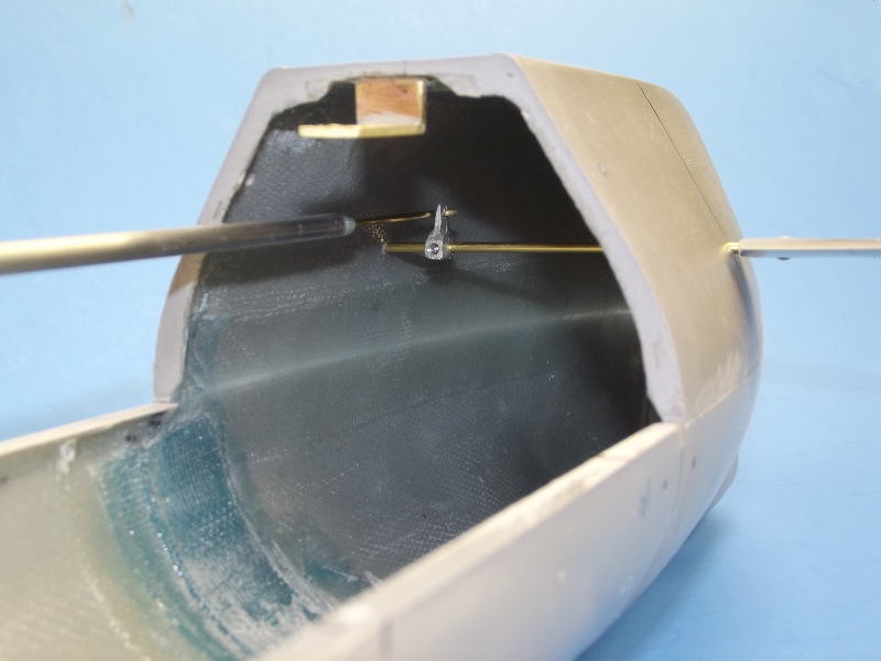
You'll note the use of a large diameter (1/4") aluminum pushrod -- here, made up to the bow plane operating shaft bell-crank. This light weight, yet stiff, pushrod prevents flexing as the control surfaces are positioned against the load presented by flow forces. Each end of a pushrod terminates in 1/16" brass rod. These rods suitable for make up to the bell-crank through a Z-bend at one end, and a magnetic couplers at the other end of the pushrod. In the above photo you can make out the securing set-screw of the bell-crank which makes it fast to the bow plane operating shaft. Interfacing the small diameter brass rod and the much larger diameter aluminum tube is an adapter. This adapter made from a sprue of polyurethane resin, bored and turned to integrate the brass and aluminum pieces. The assembly made fast with CA adhesive. 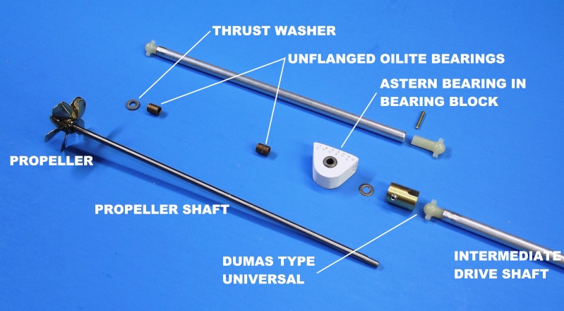
Working out the running gear on this NAUTILUS model is easy: The two beautifully cast and finished brass propellers, and a molded in place propeller shaft bore (stern tube) that runs straight and true through each horizontal stabilizer are provided. All that is required of the kit assembler is to procure and install an un-flanged Oilite bearing at each end of a stern tube; come up with bearing blocks and an astern bearing; and provide intermediate drive shafts that fit between the propeller shafts and SD motor output shaft through universal couplers. The after Oilite bearing, against which the propeller pushes, serves to transmit the 'ahead' thrust load to the hull. The forward most bearing addressing the backing thrust load through its bearing block which is bonded within the hulls stern. 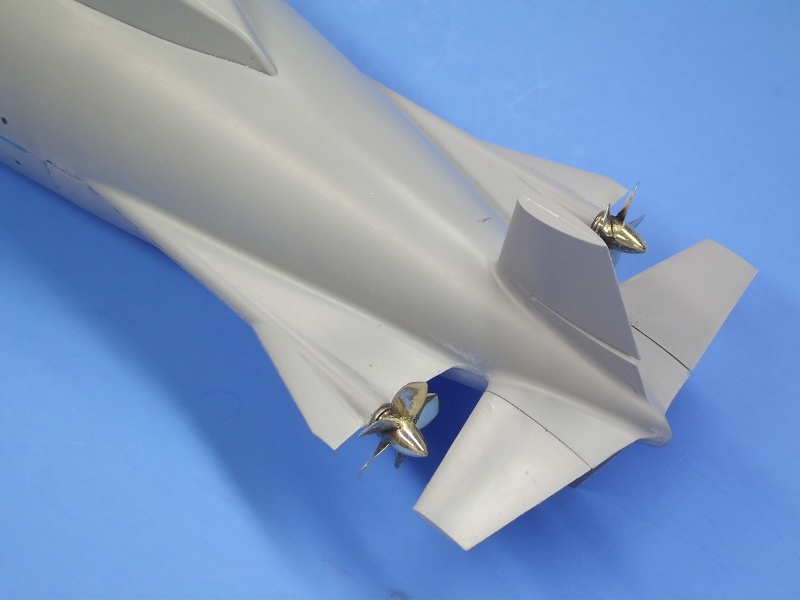
Beautiful, isn't it? Other than just a little file work to knock down some flash at the perimeter of the appendages, I have not done a thing -- this is how tight and clean the stern is once the parts are assembled. This kit is a marvel of precision, good kit design and manufacture on display! Into the extreme after end of the stern tubes are set and glued ahead Oilite bearings, against which is a thrust washer, pushed against by the face of the propeller hub. The GRP stern piece comes to the customer assembled with a perfectly true stern tube through which each propeller shaft passes. As mentioned before, I substituted imperial sized shafts for the kit provided metric. As this undersized those items it was an easy matter to sleeve up the control surface operating shaft openings (which make for simple bearings) to pass the shafts that operated the rudders, stern planes, and bow planes. At the stern, the only tricky task was to lathe turn the little 1/4" outside diameter intermediate and ahead Oilite bearings. This operation required to make them fit the existing propeller shaft stern tube bore. Stock 1/4" outside diameter astern Oilite bearing were placed in custom made 'astern thrust blocks'. 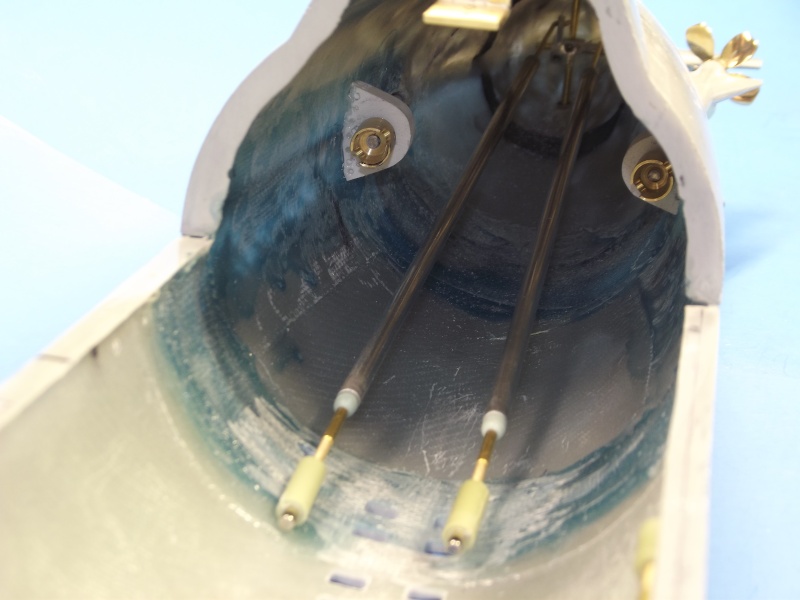
Looking aft into the hull we see the CA secured astern thrust blocks. Each propeller shafts forward end passes through the astern thrust bearing set within its thrust block. Once installed, the after face of a Dumas type universal coupler presses against a thrust washer which makes contact with the forward face of the astern Oilite bearing. This is where astern loads are presented by the propeller shaft when going astern. Keep in mind that there are three bearings per shaft: 1. the ahead thrust bearing at the after end of the stern tube, against which the propeller hub (through a thrustwasher) pushes 2. an intermediate journal bearing set at the extreme forward end of the stern tube, to damp out side loads (vibration) the shaft might experience at high RPM's 3. the astern thrust bearing housed within a bearing block which in turn is bonded to the hull If you look real hard you can just make out the control surface operating shafts and the pushrod bell-cranks that make up to them. In this shot you get an appreciation how easy it is to make up stern control surfaces with a boat that makes use of two, rather than one, propellers. 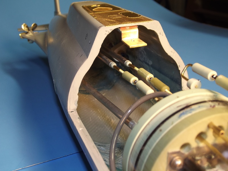
Center, near the top of the hull are the rudder and stern plane pushrods. At the extreme forward ends are magnetic couplers which make up to their counterparts that run from the after end of the SubDriver, the SD pushrods passing through watertight seals and on into the cylinder were each makes up to a servo. The magnet of each magnetic coupler makes a press-fit within a resin foundation that, in turn, accepts a threaded rod bonded to its pushrod -- turning the magnet foundation permits fine adjustment of pushrod length. Between the propeller shafts and the SD motor shafts are intermediate drive shafts. These make up at each end in Dumas type universal couplers. These shafts transmit only torque, no axial loads, so no connectors are needed -- the intermediate drive shafts simply slide into place as the SD is installed within the hull. 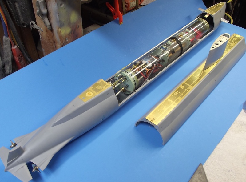
This is how the SD integrates within the hull. The SD indexes with the hull through a single brass pin set within the Velcro strap foundation -- this pin, which engages a hole in the bottom of the central ballast tank -- prevents axial and lateral motion of the SD once in place. You can make out the black Velcro strap that securely holds the SD down on the two saddles . The saddles position the cylindrical SD to that its longitudinal centerline falls shares that of the hull. The removable SD can be installed/removed in seconds. The interface between the hull and SD propulsion, ballast, and control sub-systems are the two propulsion intermediate drive shafts, three magnetically coupled control surface pushrods, and the flexible hose that runs from atop the SD to the sail located snorkel induction mechanism. 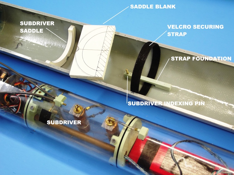
A closer look at the saddles and Velcro strap that index and hold the SD within the hull. The strap foundation came from one of the submarine plastic kit r/c conversion fittings kits I produce. The two saddles were cut from laminations of PVC sheet, layered to a thickness of 3/8". The strap foundation was secured with two 2-56 machine screws. The saddles were CA'ed in place after establishing where the bottom flood-drain holes went - I didn't want the saddles to straddle open holes, so I waited till that work was done before determining exactly where in the hull the saddles would go. Plotting and opening up the flood-drain holes will be covered in the next installment of this WIP. |
|
Bitte Anmelden um der Konversation beizutreten. |
|
part-6
The flood and drain holes on the bottom of this NAUTILUS model are both an appealing scale feature and a vitally important element in the operation of this wet-hull type r/c submarine. Through these openings water passes in and out of the hull as the SubDrivers (SD) ballast tank takes on and discharges water. And what better way than through the scale openings in the bottom of the hull? As the kit is primarily designed to be a dry-hull type, there is little in the instructions and no markings on the hull, indicating these flood-drain holes on the bottom of the hull -- it's left for the customer configuring the kit for wet-hull operation to determine the location, size and number of bottom flood-drain holes. I identified drawings prepared by the much published (and authoritative) Jim Christley That did a pretty good job of identifying the NAUTILUS flood-drain holes. I scaled his drawing up and used them to make a marking template. Marking the bottom of the hull the location and shape of the flood-drain holes is only part of the task. The GRP hull, essentially silicon glass fibers bound in a hard resin, requires proper tool selection and use to be cut and ground effectively. The single removable water tight cylinder (WTC), or SubDriver (SD) as I call it, is aligned to the hull through a single indexing pin, and is held down onto two supporting saddles set at the bottom of the lower hull. I'll demonstrate that interface in this installment of the WIP. 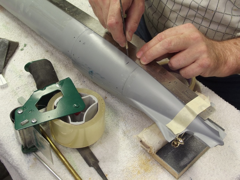
There was no molded-in place longitudinal cheat line at the bottom of the GRP hull pieces. No big deal, I determined the dead-center bottom with a piece of radially placed masking tape -- flopping it from being wrapped on one side, then the other and adjusting quarter-radius marks on the tape until I had a radius line on the tape of a length that worked each side of the hull. Using the marked tape as a measuring tool I placed two BDC points on the hull then scribed a longitudinal cheat line, connecting those two points, as illustrated in the above picture -- this engraving became the bottom hull longitudinal datum line off which I radially distanced the flood-drain and main sea water hole locations. 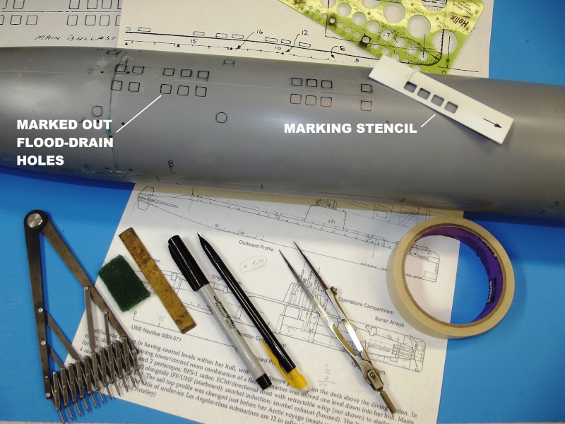
​ I found a Jim Christley illustration in one of my books that indicated credible locations and approximate lengths of the bottom flood-drain holes -- the ports through which seawater went in and out of the submarines ballast tanks. His drawing also indicated four other very important penetrations in the hull: the two sets of main sea water suctions and discharges. Though there was no way to garner from this small and slightly smudged illustration the distance the flood-drain holes were from the bottom centerline, I made a best-guess using an old training-aid-book from my submarine days on the WEBSTER. Resolving those documents (and a 1/48 drawing left over from a RTR DeBoer Hulls NAUTILUS job done over a decade ago) to the 1/86 scale of the NAUTILUS model I'm currently assembling, I determined their shape and stand-off distance -- and from that I worked up a flood-drain hole marking stencil from plastic sheet. A Draftsman's circle stencil was used to mark off the propulsion main sea water suctions and discharges -- one set on each side as the NAUTILUS' hull. 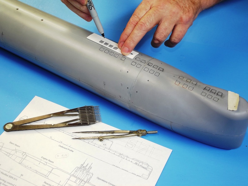
I worked out the ratio between the Christley drawings and the hull, applied that to a set of proportional dividers and lofted the flood-drain hole sizes and distances between centers to a .025" thick piece of polystyrene plastic sheet. The marked off holes then punched out with drill and files to produce a generic flood-hole marking tool. Here you see it put to work marking out some of the ballast tank flood-drain holes in the forward group. 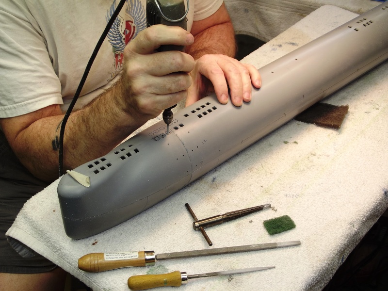
The flood-drain holes were started with the carbide bit -- this tough, very hard coated tool makes quick work of hard substances such as glass. Glass is the 'G' in GRP. I segregated all my cutting tools into three categories: those for plastic and brass alloys; those for iron and stainless-steel; and those tools condemned to cut GRP. How does a cutting tool get awarded the prestigious honor of chewing on glass? With use and age that tool has become a bit dull, its got one foot in the grave. So, its final use will be heroically grinding away GRP parts. That's how tough GRP is on tool-steel -- once that tool has tasted GRP, it's a gonner. 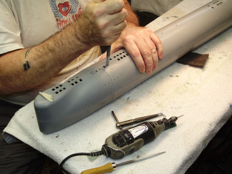
Over the decades I have assembled quit a collection of files of various shapes, cut, and sizes. here I've selected a square sectioned file to finish off opening the square holes -- holes initially punched out with a moto-tool carbide rasp. See those files? They'll be in a land-fill by this time next year. 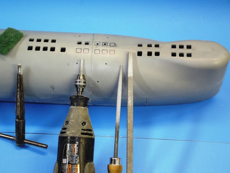
The hand-reamer to the left was used to pen up the big circular main sea water openings near the stern. The moto-tool, equipped with a carbide rasp was used to make the initial opening for both circular and square holes; The two square sectioned files were used to give shape to the square holes. From stencil manufacture, mark-out, to final hole trimming took me the better part of an afternoon. Knowing what tools to assign to the job and how to use them is the key to quick, clean work. 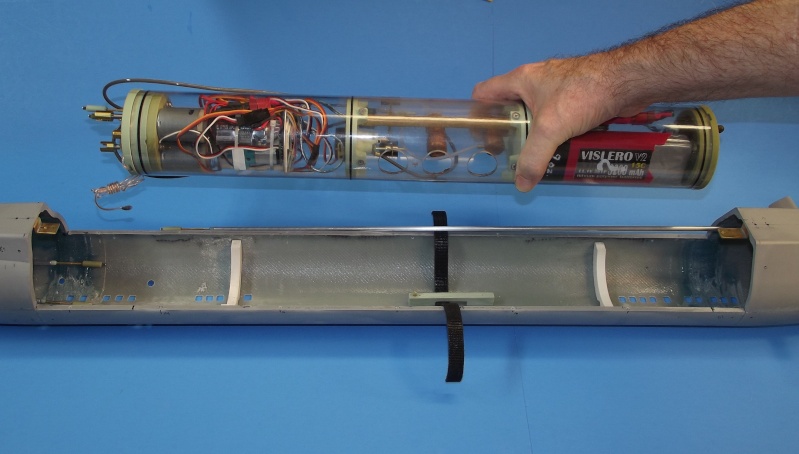
Holding the SD over the lower hull, illustrating the SD securing hardware in the lower hull that secures and indexes it once installed. The white items are the two CA'ed in place PVC plastic saddles. The foundation piece, that both retains the single securing strap, and supports the SD-to-hull indexing pin is in the center. The indexing pin engages a hole in the bottom of the SD's ballast tank, retaining it and keeping the SD from rolling or sliding once the Velcro strap is made up tight. 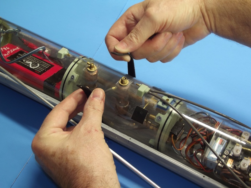
Demonstrating how the Velcro strap is employed to hold the SD down tightly onto the two mounting saddles. The bottom of the strap runs under and around the strap foundation pieces which in turn is secured to the bottom of the hull with machine screws. The double-sided Velcro (hooks on one side, hoops on the other) is slightly elastic permitting a very tight pull-down of the SD onto the saddles. The strap and the indexing pin makes the SD one with the hull, insuring no pushrod backlash or binding of the running gear. 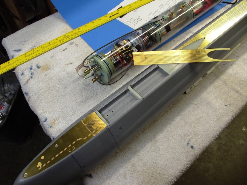
The thin, very delicate acid-etched deck pieces might become an operational problem. My biggest fear is that some idiot, either launching or retrieving this model, will accidentally push his fat thumb through the very delicate, minimally supported, center acid-etched deck pieces. To be fair, there are underlying supports for the central acid-etched deck pieces; Andreas has provided transverse GRP cross-bracing upon which portions of the acid-etched deck will sit. The issue is, I don't think there are enough of them -- a lot of flimsy deck remains unsupported. It's my intention to double the number of below deck braces to give this thing a chance of getting through at least one season of operation without a damaged acid-etched deck! Contributing to the center deck weakness problem is the incorporation of a trough in the top of the hull. Why? Keep in mind that this kit was originally designed as a dry-hull type r/c submarine. The trough was built in to reduce the boats total submerged displacement. Had the kits hull been capped at its deck level (which would have solidly supported the center portions of acid-etched deck) doing so would have resulted in a hull displacing much more water than had the trough been incorporated. More above waterline displacement means a larger ballast tank, and a larger ballast tank takes up more valuable volume within the hull, making installation, adjustment, and replacement of internal devices a Plumber's nightmare. As it is now the acid-etched deck is divided into four pieces: The forward most piece sits flush at the bow with the entirety of the piece supported by the hull; same with the after most acid-etched piece. The center section, with the trough, has only a few narrow GRP transverse (cross-braces) to support the very flimsy and easily pushed in acid-etched deck. However, the acid-etched deck has narrow transverse solid areas where the actual submarine had these deck re-enforcing cross-braces -- I'll place additional GRP cross braces in the trough, under those solid areas, to add support to the deck pieces over the trough area. |
|
Bitte Anmelden um der Konversation beizutreten. |
|
I've elected to represent this USS NAUTILUS model in the 'as built' configuration. The display to look as this historic submarine did as it slid down the ways at Electric boat sixty-some years ago. My God, has it been that long?
Yet incredibly we (along with our UK partners -- who were the first to get the ball rolling) managed to harness the atom for 'useful' work such a short time ago! There are subtle differences between how the boat looked then as to how it looks today as a museum ship. Originally the top of the sail was flat (not humped); there were two levels of free-flooding observation compartments with deadlights set into the leading edge of the sail; there were no sonar fairings on the deck; there was an array of large, square limber holes on the sides of the superstructure; it had five-blade propellers of traditional shape; and the stern was much more blunt of contour than it is today. Through the decades, the USS NAUTILUS has seen changes in mission as well as looks. Andreas' kit is a bit of a hybrid: The sail has the hump, yet the stern is as originally built, the old style screws are provided, there are no deadlights in the leading edge of the sail, and the sides of the superstructure are neat. However, should you elect tor represent your model as the early version, this kit contains detailed instructions and illustrations that direct you on where the limber holes go as well as how they were shaped and sized. I elected to enhance the 'step' between hull and superstructure -- a prominent feature seen on the actual boat, but lightly represented on the kit hull parts. Once I had built up this high relief longitudinal 'break' that ran around the superstructure I marked off and punched out the many superstructure limber holes. The trough at the top of the hull (there to reduce the total displacement if the kit was to be assembled as a dry-hull type r/c submarine) presents a problem in that the two void areas, that run the entire length of the trough, form voids that if not vented would entrap air-bubbles once the boat made the transition from surfaced to submerged condition. These voids had to be opened up so that escaping air from within the hull could easily make it to the underside of the deck and out open holes placed there to insure a complete flooding of the hull as the model submarine assumes submerged trim. 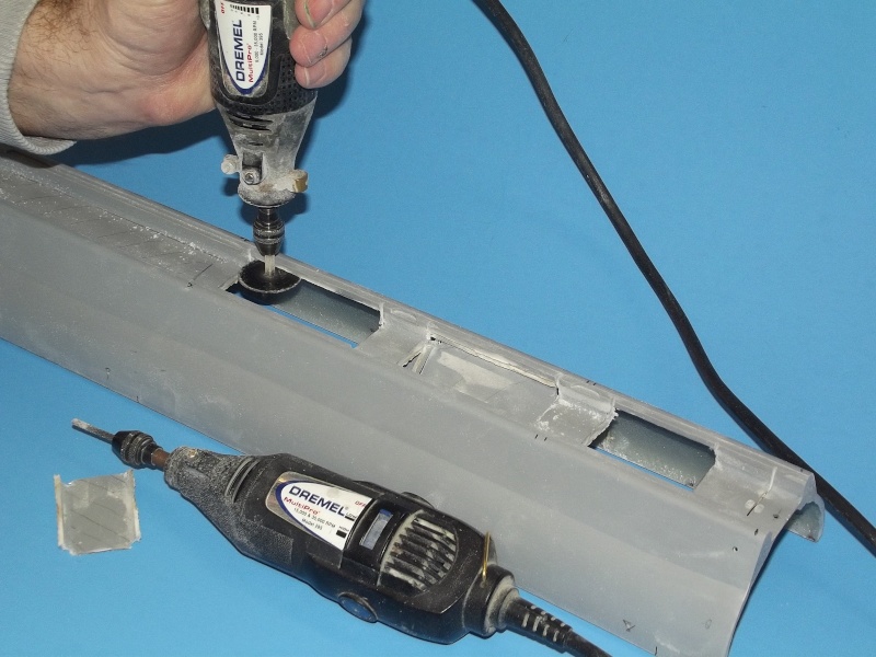
I opened up most of the void areas either side of the trough. Only the removable upper hull piece had this trough. Note that the removed portions go all the way up to the underside of the deck -- bubbles will pass from the voids to the underside of the deck, then out vent holes to atmosphere. This work done for two reasons: 1. eliminating unneeded structure above the submarines waterline reduces the submerged boats displacement -- ballast tank volume is directly proportional to the volume of water displaced by the above waterline portions of the submarine. 2. since this is a free-flooding hull (only the SubDriver within is watertight) it is vital that all air within the superstructure be vented off as the submarine transitions from surfaced to submerged trim -- opening up the top of the hull like this insures that no bubbles of air get trapped in the 'high' portions of the trough, the voids either side of it. 
I built up four layers of masking tap below where I wanted to represent the superstructure-hull slot -- represented on the kit hull as a simple angular transition between superstructure and hull. Against the top edge of this masking tape dam I built up Bondo over both sides of the superstructure. The base of this build-up, once the tape dam was removed, would overhang the hull by about .030". This greatly increased the 'look' of the scale model. 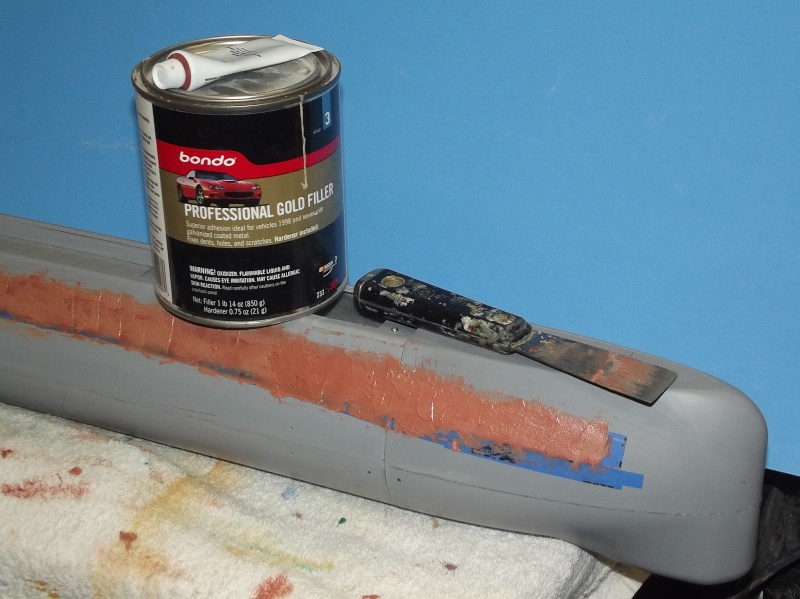
Bondo, a two-part, exothermic curing filler -- often associated with automotive body work -- Is an excellent material where conformal, tightly bonding, yet easily filed and sanded material is demanded for surface re-contouring or gouge repair. Here you see it being used to build up the sides of the superstructure to produce the pronounced 'step'; simulating the slight stand-off of the upper superstructure plating over the rounded hull underneath. Almost buried under the Bondo is the four ply masking tape used to produce this step. Once the Bondo has been knocked down with sanding blocks, to the level of the mask dams surface, and feathered up to the top of the superstructure side, the masking is removed -- it's edge producing a sharply defined step that denotes the break (artificial though it is) between hull and superstructure. 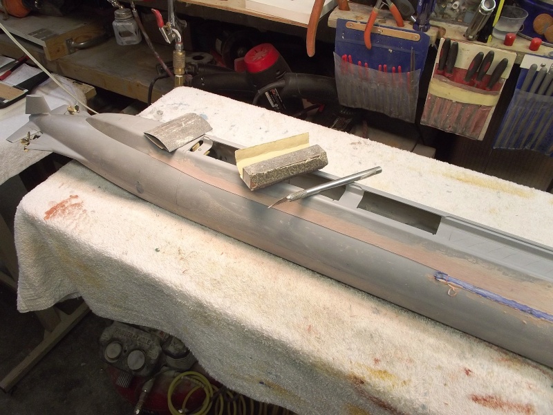
Once the Bondo had cured reasonably hard (it takes at least a day to cure to 90% of its solid state) I attacked it with descending grits of sandpaper till a reasonably smooth surface had been achieved. most of this work done with sanding blocks to insure that the sides of the superstructure assumed a flat surface. To the right you see partially sanded work with the step producing masking tape dam still in place. As a section is finished the tape is pulled away revealing the simulated superstructure-hull step. There! … looks just like the real thing! 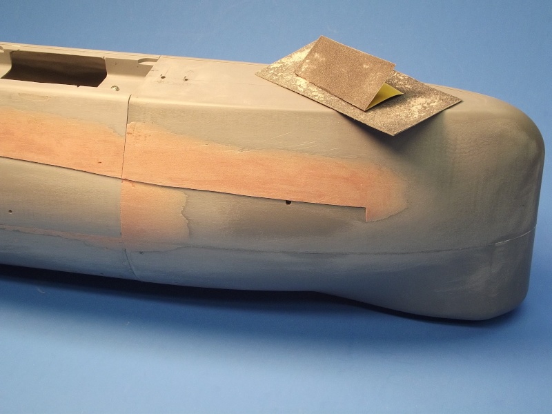
Wherever possible you want to to use a sanding block on long, simple curved surfaces, such as the Bondo build-up over the existing GRP. To refine the 'slot' I used CA adhesive stiffened pieces of sandpaper. Note that while I was working the slot I also faired in the slight miss-match between bonded bow hull pieces. Some consider the automotive type fillers as unsuitable for r/c submarine use. That has not been my experience at all. Once well protected under coats of primer and paint this otherwise water absorbent material will stand the tests of time and use -- I have twenty-year-old r/c submarines, coated with Bondo like material, that today evidence no failure of the filler. Bondo is our friend! 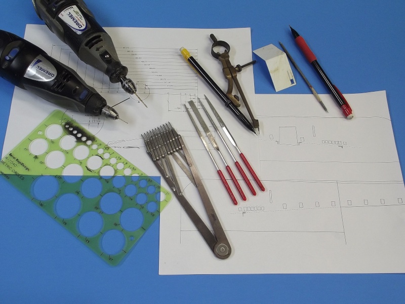
The square limber holes on the sides of the superstructure run all the way up to either side of the bow. Only at the bow do these flooding holes differ in shape and size -- becoming a bit smaller and spaced very close together. All the dope about the shape, specific size and location of all limber holes is presented on two of the 'instruction' pages that accompany this very complete r/c submarine model kit. The illustrations are presented in orthographic, isometric and 'exploded' form. The task of lofting the dimensional information (stated and drawing specific) onto the surface of the model was accomplished with metric scale (this is, after all, a European based kit), proportional dividers, two-point dividers, marking templates, pencil and scratch-awl. 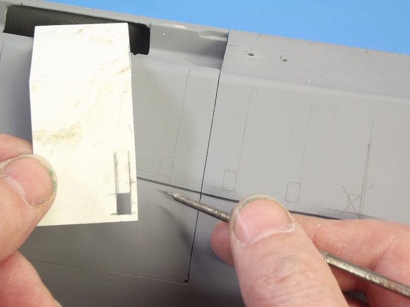
I took a piece of .010" plastic card, trued it up to a perfect rectangle, then scribed a perpendicular line in the middle, and bent it to the angle described by the deck and superstructure side. I fixed that bend with some CA on the inboard side of this marking-scribing template blank and used to to mark verticals (the deck being the datum plane here) on the side of the hull. Each vertical line falling along the point where the leading edge of a square shaped limber hole would go -- those points indicated, in mille-meters, on one of the instruction sheets. You see those vertical pencil markings in this photograph, along with the scribed in outlines of each limber hole. You might ask why not mark the holes with a pen or pencil. Sure, would have been simpler and less work, but a scribed line is much narrower than an external marking (ask any sheet-metal guy!). The difference between a pencil or scribed line is the difference between a sloppy hole and a tight hole. (Sorry -- a left-over from Torpedoman A-school). 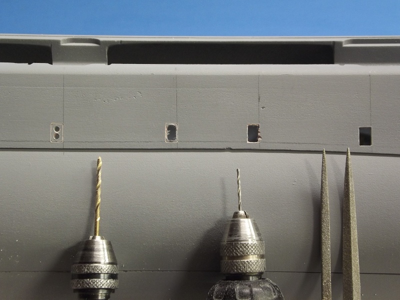
And here we have the four steps (evolutionary progression) of how I get from marking to completed hole: 1. at the extreme left we have the initial start of a square limber hole, two 1/16" holes punched within the previously scribed limber hole outline, that engraving done with the aid of a special scribing stencil 2. the the limber hole has been refined significantly using the same drill bit as a mill with the flutes doing the cutting, pushing the bit up-down-left-right, keeping the cut within the hole boarder defined by the engraving 3. second from the right is the further refined square hole, done with the smaller bit worked as a mill -- it's smaller diameter produces a tighter radius at the hole corners, the small bit is harder to hand-steer than the larger bit, so it's only used after the hole has been roughed out with the big bit 4. And the file refined square hole to the right using square and three-faced diamond files 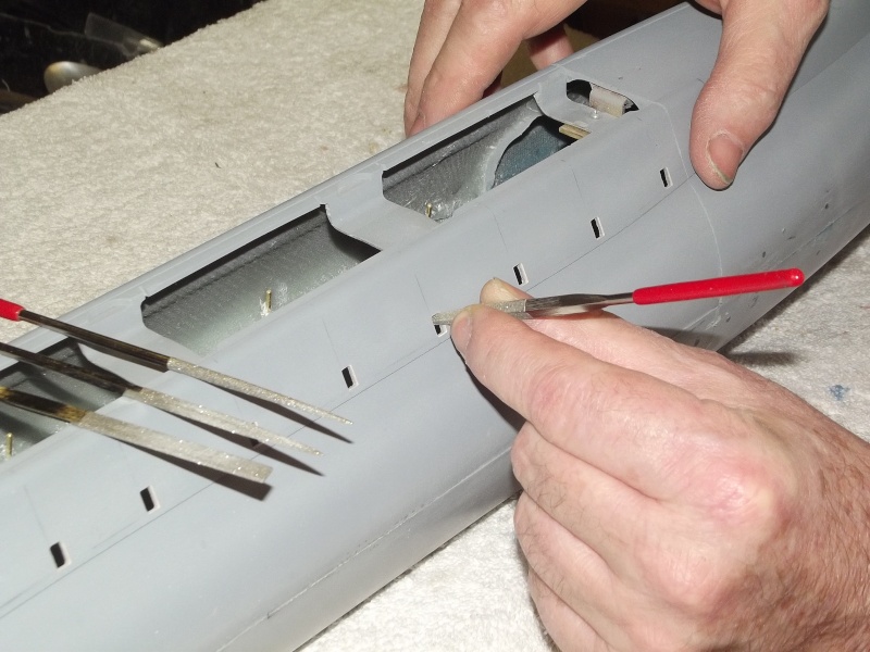
Diamond dust coated files are the best tools for GRP detail cutting. They will never dull, and the industry has produced an incredible variety of these files in all sizes and cross sections. I found the most useful files for this job to be straight, Jeweler's sized square and triangle sectioned diamond shape. Those two files to the extreme right. Also seen to advantage here are the open portions of upper hull -- done to reduce submerged displacement and to properly vent the free flooding hull when the model is commanded to dive beneath the surface. 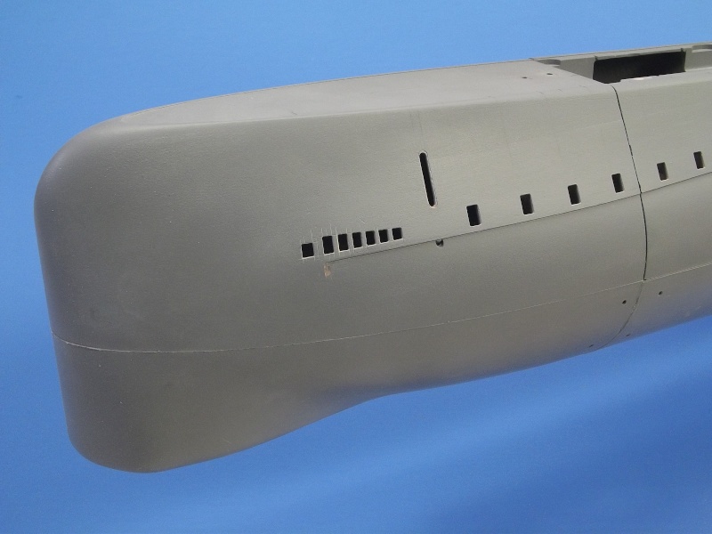
Though the surface of the hull has been beat up with knife, file, rotary bit, and scribing over-strikes, the depth and severity of those boo-boo's are quickly fixed with air-dry touch-up putty and #400 grit sanding sticks used wet. A quick shot of automotive lacquer primer (DuPont's Nason 421-23 gray primer) shows off the shadow thrown by the slot between superstructure and hull. This slot runs all the way aft, around the turtle-back and to the other side. Amazing what you can achieve with a little Bondo! Roughly speaking, on the actual boat, this slot is the demarcation line between external hull and superstructure. It is through this slot that most of the flooding/draining water passes in/out of the free-flooding superstructure as the submarine transitions between surfaced and submerged trim. The USS NAUTILUS, as built -- in a time where marine Architects where still in the 'submerge as quickly as you can' mind set -- the square flood-drain limber holes were there to augmented the flooding/draining rate of the superstructure. However, as the navy came to realize that the mission of the submarine would forever abandon the need to cruise on the surface, the noise producing limber holes were (for the most part) plated over. This streamlining measure improving both the hydrodynamic and acoustic performance of the hull. As I wanted to represent the early version of the NAUTILUS I was compelled to incorporate these iconic limber holes during assembly of this kit. Extra work? Sure. But well worth the effort. |
|
Bitte Anmelden um der Konversation beizutreten. |
|
Part-8
A notable departure from the kit instructions was my inclusion of additional sub-structure re-enforcement cross-braces. These to provide a more sound support under the very flimsy photo-etched (PE) deck pieces. Though the kit supplied GRP transverse deck pieces served this function to a degree, I determined that there were not enough of them to do the job adequately. My fear is that I or some other idiot, while handling the model would accidently damage the very fragile PE deck, ruining it. So, better now to strengthen the deck sub-structure than to repair a painted and weathered model after the inevitable deck damage occurred. Concurrent with that I began the task of representing the clear deadlights at the leading edge of the sail. I could have painted these on with a gray or silver color later – that would have been the simple solution. However, nothing looks like clear windows like … well … clear windows! These windows which provided visibility from within the sail to the forward deck were used by watch standers while the submarine cruised around on the surface in rough weather. There were three levels of these deadlights – the lower two levels represented by blocks of clear acrylic sheet, and the top level, forward of the bridge, would differ in that its deadlights would be represented by a build-up of clear, 12-hour cure epoxy glue – employing a very neat process advocated by David Manley. More on that later. 
Though the kit provides transverse GRP deck supports, I believe that the very flimsy PE deck pieces will be subject to handling damage (pushed in by fat fingers!) if additional sub-structure bracing were not provided. That’s what you’re seeing here: .015” thick styrene sheet transverse deck braces being installed atop the superstructure. The position of these additional cross-braces fell under (and was hid by) a corresponding all-metal transverse section of the PE deck. Under normal lighting conditions these sub-structure braces will not be apparent through the open slots between simulated wood planks of the PE deck pieces. 
You can see how I’ve arranged the additional sub-structure cross-braces, each sitting under the transverse all-metal portion of the slotted PE deck pieces. Later, after most of the painting is done, the PE deck pieces will be secured atop the superstructure with RTV adhesive. Note how the top of each cross-brass has been outfitted with slots. These to permit the quick longitudinal movement of entrapped air bubbles so they can move about and find a vent hole in the deck so they can escape. Entrapped air within a wet-hull type r/c submarine is a major problem and one has to be ever mindful to provide for complete venting of the hull as it makes the transition from surfaced to submerged trim. 
Making me the liar, this flash photography does show the additional transverse sub-structure elements added to strengthen the fragile PE deck. However, in the real-world, you won’t see much past the slots of the deck. This trick of lighting does show how I’ve placed the additional cross-bracing under the transverse ‘solid’ portions of PE decking. I must comment again at my amazement at how well everything on this CAD designed and CNC and printed tooling of this kit insured all parts fit together almost perfectly-this thing literally falls together out of the box! 
A Machinist’s surface-gauge was used to scribe the upper and lower edges of the yet-to-be-established deadlights. A right-angle triangle was used to guide a scribe as I cut in the deadlight vertical edges. Such lay-out precession was needed for the bridge deadlight cut-outs, but was over-kill for the plugs of clear acrylic actually used to represent the clear faces of the lower platform deadlights. A holding fixture was cut from shelving stock and the sail screwed to it using the same fasteners and foundations that secure the sail atop the NAUTILUS’s hull. 
The ballast sub-system employs a float activated snorkel valve within the sail. It was necessary to establish the where the bottom of the mast foundation piece sat within the sail so the snorkel could be made so it would not project above that line. On the outside of the sail I marked where the bottom of the mast foundation piece terminated and designed the snorkel mechanism to occupy the space beneath. 
A trick that goes back at least a century is the use of clear plastic plugs, inserted into the portion of model where you want windows, and to then grind the outer surface of the plastic (usually acrylic) to conform to the outer contour of the model. Once the face of the clear part is ground and polished back to an optically clear item, the window frames are made by masking over where you want only clear areas to be, then paint, and remove the masking. That’s what’s going to happen here to the two lower platform deadlights. Deadlight is navy-speak for windows. Two ¼” thick pieces of acrylic sheet have been roughed out to approximate shape. Once set into the leading edge of the sail each is CA’ed in place, and ground, filed, sanded, and polished to conform to the curvature at the leading edge of the sail. The drill was used to rough out the individual open deadlight ports up where the bridge will go. Diamond files were used to refine the square openings. Later these openings will be filled with clear epoxy glue. More on that later. 
The solid acrylic pieces filed and polished to conform to the leading edge of the sail. The bridge open deadlight frames will later receive epoxy lenses. But, once it’s all masked out and painted you will be hard pressed to see the difference in materials and fabrication methodology between the three platform deadlights. I could not use the acrylic trick on the upper deadlights as there is little space between the deadlights and forward section of bridge well – a cast resin piece that will later 
The installed pieces of acrylic plastic within the two lower platform deadlight positions has been ground, filed, sanded, and polished to follow the contour of the sails leading edge. The slabs of acrylic plastic were fine for the two lower levels, but not for the bridge level as those deadlights had to be of a thickness little more than the thin GRP of the sail. 
When painting over masked clear parts you always want to go with the final color, from beginning to end. If you don’t, then the different colors (gray and/or red primer for example) will result in a disparity of color at the edges that denote transitions from clear to colored portion of the model. So, if the final color will be a dark, dark, gray (the case with this model), then that’s the only color you will shoot over the clear part masks. Once the deadlight masks are in place I’ll lay down the first of many layers of final color. Paint does not typically have the heavy fill ability of a thick primer, but multiple coats will eventually get the job done around the deadlights. 
The bridge level set of deadlights has yet to receive its clear lenses. The two lower platforms have had their individual deadlights (each set actually a single hunk of clear acrylic plastic) represented by pieces of masking tape followed by a coat of dark-gray paint. Here, with the masking removed, we see what appear to be closely spaced, deadlights along the two lower sail platforms. |
|
Bitte Anmelden um der Konversation beizutreten. |