Willkommen, Gast
Benutzername: Passwort: Angemeldet bleiben:

THEMA:

Err:522 7 Jahre 11 Monate her #35099

  • Dr.Schmidt
  • Dr.Schmidts Avatar Autor
  • Offline
  • Kommodore
  • Kommodore
  • Beiträge: 542
  • Dank erhalten: 2
...

Bitte Anmelden um der Konversation beizutreten.

Err:522 7 Jahre 11 Monate her #35100

  • Dr.Schmidt
  • Dr.Schmidts Avatar Autor
  • Offline
  • Kommodore
  • Kommodore
  • Beiträge: 542
  • Dank erhalten: 2
Part-9
A statically diving type submarine submerges by taking on water ballast (variable ballast). The weight of the ballast water equal in weight to the water displaced by those portions of the submarine formerly above the surface.
The more structure above the surfaced submarines waterline, the more ballast water needed to counter the buoyancy of those structures once they are immersed in water. Good design practice would have you make the ballast tank as small as possible for two reasons:
First, is to minimize the volume given over to the ballast tank itself, leaving room for other devices needed to animate the submarine.
And less ballast water to be shoved in and out means less energy expended to move that water. Usually, as in this design, the air in the ballast tank is simply vented to atmosphere, done by a servo – not much energy expended there. However, to empty the ballast tank of water an air-pump has to be run, and that means a drain on the battery and wear and tear on the pump controller, pump, and its motor. Also, as my SD also employ’s an emergency gas back-up ballast blow sub-system, there is the kinetic energy stored within an on-board bottle of liquefied propellant, that energy given up each time an ‘unscheduled’ emergency surfacing occurs. We want to husband the vessels energy reserves. So ...
... Small ballast tank-- good; big ballast tank -- bad.

In a wet-hull type r/c submarine superstructure and sail wall thickness is the main driver of total above waterline displacement. Most of the appendages are solid cast items, and they too contribute to the total above waterline displacement.
This kit, designed and manufactured by a model aircraft guy – which makes him a GRP weight conscious fanatic -- has above waterline structures of very thin section. That’s why this r/c submarine kit, even though it represents a boat of high freeboard, requires a relatively small ballast tank.

(GRP and polyurethane resin have specific gravities close to 1, so in this game weight pretty much equals displacement).
Unfortunately, when I sized the ballast tank for this model, I still managed to wildly underestimate the total displacement of the above waterline portions of the surfaced model NAUTILUS. The first trimming trail with that SubDriver (SD for short, or for you old-school types, WTC) revealed that shortcoming immediately. Compelling me to build another SD with an enlarged ballast tank.
The SubDriver is a removable system comprising the propulsion, control, and ballast sub-systems that animate the model. I’ll outline the SD’s design, fabrication and functions in a later installment.


The two machine screws that hold the upper hull down upon the lower hull are accessed through holes drilled through the PE deck – one forward, one aft. Great care was taken to secure the deck pieces onto the drill press bed: any drill chatter would easily tear the thin brass piece to shreds. Also, long before I determined securing screw locations I found spots on the PE deck pieces that were solid, and not impossible to drill slotted portions.
And that’s the case here. Note that the forward upper hull securing screw access hole will run through the PE deck where the solid deck hatch rescue-bell seating foundation is.


With the basic submarine structure completed and the SD and other internals worked out, time came to install the fixed ballast weight and buoyant foam – all arranged to work with the variable ballast water to set the boats displacement for both surfaced and submerged trim.

The trick is to make the center of gravity and center of buoyancy well distanced vertically; and for these two collectives of force to shift longitudinally, in unison, as the boat makes its transitions between surfaced and submerged trim.
Experience tells me that a four-foot long wet-hull type r/c submarine requires at a minimum two pounds of fixed lead ballast weight as low in the hull as possible. Here I’ve broken out some ingots of lead for a trial installation of fixed ballast weight.
A single screwed submarine would need more fixed lead ballast to better counter the torque of the propeller. However, as this submarine has two counter-rotating propellers (net torque is zero), I could get away with two pounds worth.


The USS NAUTILUS, in surface trim, has a very distinctive waterline: A high freeboard (distance from waterline to top of deck); the bow high, and the stern low. Unlike so many of the cold-war era American submarines, this conservatively designed -- first vessel to be nuclear powered -- submarine embodied many of the post-war, old-boat characteristics: hull form optimized for surface cruising; wide flat deck; and a high freeboard owing to its (by today’s standard) a significantly large amount of reserve buoyancy.
Before starting the trimming operation – a process, by trial-and-error of the amounts and location of fixed ballast weight and buoyant foam – I marked out onto the hull, with a wide Sharpie pen, the submarines surface trim waterline. The objective is to have the boat, with dry ballast tank, float at this waterline in surface trim; and, with a flooded ballast tank, to project only the top of the sail above the waters surface in submerged trim. The marking was laid down with the model rubber-banded to a flat work surface, pitched up the correct amount (that angle established by checking with a Machinist’s surface gauge as the bow was shimmed upward), and the waterline marking tool run around the model, laying down the waterline where it should go.


The first attempt to trim the boat revealed that I did not have enough ballast tank volume to get the boat up to the designed waterline once the tank was blown and emptied of water. From submerged trim I needed a weight of ballast water equal to the weight of water displaced by all the above waterline structures. Didn’t have it! Damn thing sat low in the water with the tank dry. The ballast tank was too small. Who was the dumb-ass who designed this system anyway?!.....
Nuts!


Nothing for it but to make a new SD with an enlarged ballast tank.
(Two, actually: one to replace my first attempt at the SD, and a second one for Andreas who’s putting together a wet-hull version of this kit back home in Germany)

The new SD features a ballast tank possessing 150% the volume of the first. Note that I retained the initial SD cylinder length by giving up space in the forward and after dry sections of the cylinder.
The aft dry section had excess space so that was easily given up to the forward section of ballast tank by moving the after ballast bulkhead aft a bit more. The forward dry section, containing the battery and mission switch was shortened by simply going to a shorter battery – cramming two of them in there and wiring them in parallel, giving the same capacity of the single long battery. The forward ballast bulkhead moved forward. Other than the bigger ballast tank and some minor relocation of ballast sub-system components, the length, function, and dry weight of the short and long ballast tank SD’s is identical.


Submerged trim is worked out first. The ballast tank is flooded. Once that’s set, you establish surfaced trim.
Yes, with all that foam hanging off the model it looks like hell.

Just the top of the sail projects above the water as the boat stabilizes at zero pitch and roll angles. Perfect submerged trim for a typical r/c model submarine equipped with a ballast tank. This is the condition of the submerged boat once the correct amount and location of buoyant foam has been established.

Working out foam amount and location to the outside of the hull is a lot easier than stuffing it within the hull and hoping you got it right. This way, the trimming is done in one, quick, sitting, without having to yank it out of the water numerous times.

“Are we done yet??!!!!”
Surface Trim, the ballast tank blown dry.
Some of the buoyant foam has been moved vertically, either above or below the surfaced waterline – the objective to get the boat to float at the designed waterline. There is more ballast tank volume than that needed using the new SD. That’s a good thing! The higher the center of buoyancy is over the center of gravity, the more statically stable becomes the vehicle.
Submerged and surface trim fixed, the model is taken back into the shop and all that foam is glued to the inside surfaces of the hull and superstructure.


The laborious process of shifting all that foam from the outside of the model to its inside has begun. It’s vital that the buoyant foam you select is of the closed-cell type. The blue and pink polystyrene expanded foam is of this type. Unlike open-cell type foam (usually white), the closed-cell type will not water-log over time. There is absolutely no need to ‘seal’ installed closed-cell type buoyant foam.
Here you see the installed fixed lead weights, and foam pieces ready to be installed within the hull. Note that some of the foam has already been shaped and bonded within the upper hull half.


The important thing is to get the longitudinal and vertical position of the foam correct. What was established during the trimming operation, placing the foam on the outside, now has to be replicated as the foam is glued to the inside of the model.

Bitte Anmelden um der Konversation beizutreten.

Err:522 7 Jahre 11 Monate her #35117

  • Dr.Schmidt
  • Dr.Schmidts Avatar Autor
  • Offline
  • Kommodore
  • Kommodore
  • Beiträge: 542
  • Dank erhalten: 2
Davids Jungfernfahrt...meins fährt heute:

The first open-water run of the 1/87 USS NAUTILUS r/c submarine kit I acquired from Germany. Produced by Andreas Schmehl this is an easy to assemble and drive r/c submarine.

This outing presented in the following video was to establish surfaced and submerged turning radius. I find this to be a well running model submarine both on and under the surface. The initial run of this boat was in the rather confining boundaries of a local swimming pool which did not give me the opportunity to maneuver the model with any real freedom. However, that all changed when I went to some open water, as you can see in the video.

The model employs a Caswell-Merriman SubDriver -- the system that controls, propels, and manages ballast water. The system is removable and easy access to its devices through the two end bulkheads is quick, easy, and assured.

This SD, customized specifically for this r/c model submarine kit, will be available soon through the Caswell catalog.

I have posted the video to Youtube.


David

Bitte Anmelden um der Konversation beizutreten.

Err:522 7 Jahre 11 Monate her #35120

  • Dr.Schmidt
  • Dr.Schmidts Avatar Autor
  • Offline
  • Kommodore
  • Kommodore
  • Beiträge: 542
  • Dank erhalten: 2
Meins ist heute gefahren. Was für eine Spaßfahrt. Es hat aufgetaucht schon nen ordentlichen Wendekreis, aber getaucht gehts schon viel besser. Hab es dann auch mehr unter als über Wasser gefahren. Sher gute Tiefenkontrolle trotz der starren Bugtiefenruder. Hier profitiert man von den hinteren Tiefenrudern direkt im Propellerstrom.

Die einzigen Spaßbremsen: Ordentlich Farbe am Rumpfunterteil verloren....über ein paar Steine geschrappelt. Der Lack hält auch nicht sonderlich gut. Beim nächsten wieder Epoxyprimer. Und der Fahrakku macht jetzt beim Aufladen Zicken....wahrscheinlich nur ein Balancer-Kabel.

Aber alles in allem: Sehr geil. Mein bestes Boot bisher.

Bitte Anmelden um der Konversation beizutreten.

Err:522 7 Jahre 11 Monate her #35122

  • Dr.Schmidt
  • Dr.Schmidts Avatar Autor
  • Offline
  • Kommodore
  • Kommodore
  • Beiträge: 542
  • Dank erhalten: 2
This model kit WIP installment is exclusively dedicated to the NAUTILUS’ sail. And for good reason: Much as a scale model airplanes cockpit, the sail of a submarine model is the focal point of the viewer’s attention – the ‘front office’ of the vehicle; it’s where the machines intelligence and purpose are housed. The sail is where the people are. The sail also is one of the few places where you get a sense of the dynamic of the vehicle it represents: the optical and electronic sensors rising and descending upon their masts and faring; and It’s the last thing seen as the boat dives, and the first thing seen when it surfaces.

As a display, the sail is the most interesting aspect of the model. One must do it justice if the display is to be attractive and interesting. The model submarines sail is the focal point of the display, have no doubts about that.

The sail, with all those windows (deadlights); masts and fairings; antennas; periscopes; and open bridge with its deck, compass repeater, alarm boxes, platforms and such: all items that demand special care by the model kit assembler.


Since the earliest days of submarining the conning towers -- and fairings over those conning towers if used -- featured clear windows through which watch-standers could conn the boat, surfaced or submerged.

These windows, properly called deadlights, were quickly abandoned as pressure hull penetrations with the advent of the periscope. Deadlights of any significant size present a flooding hazard should the fragile glass lens fail as a consequence of collision or close aboard explosion. In any event, even with good underwater visibility, only on rare occasions could one see past the bow of the submarine – of little utility to the helmsman maneuvering the boat while submerged.

From the 30’s onward submarine deadlights were relegated to the free-flooding portions of the conning tower fairing where watch standers would seek refuge against the waves while navigating the boat on the surface.

Today, the use of sail mounted deadlights has been all but abandoned (The Russian Rubin design bureau being the last significant advocate). With the advent of nuclear power and AIP the imperative that a submarine ride out a storm on the surface was eliminated – no need for weather beaten watch standers to duck down to a protected platform and peer out through its deadlights. Today, if it’s rough, the boat submerges and everyone enjoys the ride beneath the waves – no longer must the watch standers take green water in the face while powers puking over the side as cold water streams down their backsides (I speak from grim experience!). God bless nuclear power!

DBF … my ass!

As built, the USS NAUTILUS featured no less than three levels within the leading edge of the sail outfitted with deadlights for outside observation. The bottom platform had three deadlights; the middle platform had five deadlights; and the bridge level platform had another five deadlights. That’s a lot of Plexiglas! The US Navy finally abandoning sail mounted platforms equipped with deadlights with the introduction of the THRESHER class submarine.


The kit provided sail-top represents the ‘armour’ bulged top aft of the bridge opening. This bulg afforded a few inches of protection over the tops of the retractable antennas, induction, and optical heads – an alteration of the origional flat sail top, prompted by the famous under-ice exploits of this world famous submarine.

However, my kit is being assembled to represent the ‘as launched’ boat, with the flat sail- top. I had to make a new sail-top.

I substituted a .031” thick piece of commercially available fiberglass sheet (G-10) for the kits sail-top. This very strong material is dimensionally stable, and takes to adhesives, primer and paint very well.

Note that the G-10 sail-top piece is temporarily held to the cast resin mast foundation piece with the aid of two machine screws (seen atop the sail-top between the masts and fairings). The ability to refine the shape and position of the many sail-top holes for wells, lookout stations, masts and fairings with the mast foundation piece out of the way makes those jobs a lot easier.


The kits cast resin mast foundation piece – used to both provide some of the housing wells and supports of the masts and some of the antennas atop them – had its sides milled down and a good portion of its bottom cut away to reduce total weight/displacement. This one piece, as it was, displaced nearly one- ounce. After the cut-down it displaced about a third of that. That’s a lot of weight removed from the tallest point on the model, aiding greatly in keeping the models center-of-gravity reasonably low. This weight reduction would minimize heeling in tight turns on the surface, and would contribute to better static stability about the roll axis.

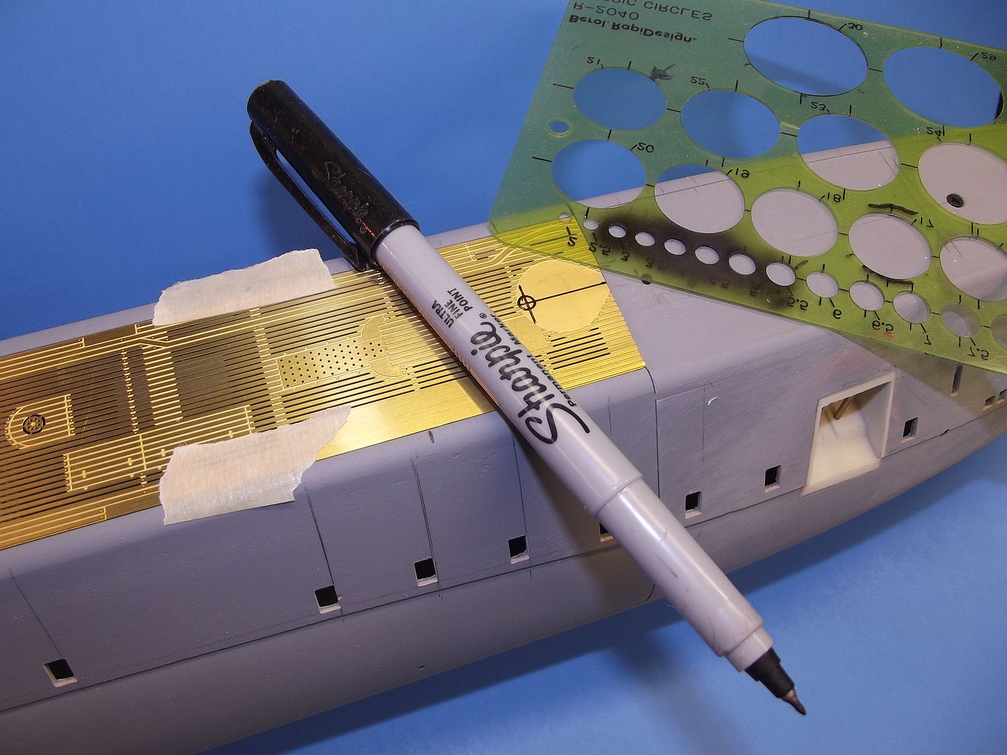
Using the original resin sail-top piece as a template, I scribed onto the G-10 the sail outline as well as the shapes and locations of the holes for the bridge, lookout stations, antenna and optics retractable masts, and fairings. Those scribed lines highlighted by smearing some artist’s oil paint over the work.


The G-10 was cut out on the band saw to outline; and the well, mast and fairing holes punched out and shaped with drills, burrs, and diamond-dust jeweler’s files.

The only two retractable masts not represented in the raised position on this model will be the communications UHF-VHF whip-antenna mast-fairings. The top of those ‘retracted’ mast-fairings represented as engraved tear-drop shaped forms scribed upon the sail-top piece.

An aluminum scribing stencil used here – the cutting done with two scratch-awls: a starting scriber with a sharp point, and a widening scriber with a blunt point to widen the engraved line. GRP material is very, very tough to scribe owing to the glass content which quickly dulls the steel tools, which required their sharpening several times during the course of this work.

As a great deal of force is applied to the scribe, both down into the work and against the inside edge of the stencil, it’s a good practice to glue the stencil in place during the entire cutting operation least the stencil shift, resulting in a ruined engraving. It’s easy enough, once the scribing is done, to pop the glued stencil off the work and scrap away any remaining adhesive from the work. On occasion I will even use machine or wood screws to hold a scribing stencil down securely onto the work.

Engraving is hard.

Filling and fairing over screw holes and scraping away glue is not.


While I was integrating the G-10 sail-top and cast resin foundation pieces I kept the two registered together with two machine screws that temporarily pulled the two pieces together. This permitted me to easily access both pieces, separately, as I cut out the holes for the masts through the G-10 sail-top, and worked to bore or sleeve the mast foundation piece bores to imperial sizes.

Damned metric-system! Can’t these people count to twelve!?....


As I stated before, big blocks of clear acrylic were employed to represent the transparent elements of the two lower platform deadlights. However, a different means of producing clear deadlights at the bridge level was required owing to the very small space between the inside surfaces of those deadlights and the front of the cast resin bridge piece.

I opened up the deadlight openings; each framed as on the prototype, and then touched the edges of these holes with a clear self-curing resin, such as epoxy glue. Now, if those openings were small enough (they were not), the strong surface-tension of the liquid would hold its form and it would bridge the entire opening as the application tool was slowly removed. The clear resin would be left to changes state from a liquid to a solid.

However, the larger openings, like these deadlights, require additional steps as the deadlight holes are way too big to be bridged in one glue application. Though it did not bridge the opening entirely, that first application of glue did build up a significant radius of clear adhesive at the deadlight corners and did build-up along the edges, reducing the amount of glue (and reducing the risk of introducing air-bubbles in later applications) needed to complete the bridging of the deadlight openings.

(You plastic model plane and ship guys may recall the ‘crystal-clear’ product for representing port holes and the like – a thick, clear-drying liquid that had the surface tension to hold form once applied with a round tool to the edges of a hole. When applied correctly the goo would hold as a film within the opening where it would be permitted to harden into a not-quiet optically clear transparency).

What David Manley taught me, and I replicated here, is to place a masking tape damn around the leading edge of the sail and apply glue from the inside, building it up thick enough to conform to the inner curvature of the sails leading edge – bridging all the deadlight openings. The outside mask insuring that the forward face of the clear glue assumed the curvature at the leading edge of the sail.

After the clear epoxy glue has cured hard the masking tape is pulled away from the sails leading edge, the inside and outside surfaces of the clear deadlights are filed, sanded, and then polished to the contours of the sail, inside and out. Deadlight masks were applied and the black (very, very dark gray) exterior painted.

Nothing to it!


It’s my practice to keep as many model assemblies separable as long as possible during the course of the job.

The entire sail assembly, only some of which you see here, is a case in point: the removable sail-top (secured to the to the sail during the in-water trimming operation and when there is a need to integrate pieces that need clearance between both sail-top and sail) permits easy access to the inside of the sail for SD snorkel mechanism integration and installation; work on the three platforms of leading edge deadlights; finish and detailing tasks to those inside surfaces of the sail seen through the open bridge and lookout stations; detailing ;installation of the sail-to-hull screw foundations; and the manufacture and fitting of the hand-rails that run both sides of the sail.


Another departure from the kit-as-provided was to make the forward ‘tub’ -- that forms the open bridge atop the sail -- removable. Accomplished by gluing four RenShape drilled and taped foundations: two to the bottom of the sail-top and two to the back of the bridge tub. Once the sail-top is glued permanently atop the sail I retain the ability to install/remove the bridge tub as required.

The two ‘L’-shaped brass items, each projecting from a side of the sail, are the mounts that interface the UHF-VHF whip antennas (represented by lengths of stretched sprue or cat whisker …. “here, kitty, kitty, kitty!”) with their respective ‘retractable’ fairing. A RenShape block glued to the bottom of the sail-top receives a whip antenna mount. Cut-outs in the sail-top and sides of the sail permitted each mount, with its attached antenna, to project well clear from the side of the sail.


The completely assembled sail-top being test fitted atop the sail. Note that all the deadlight work is done and that each deadlight has been masked and dark paint applied and the masking removed to reveal the correct number and size of deadlights that, on the real thing, permit crew observation from the three platforms within the sail – but only on the surface as the entire sail (except for the bridge hatch access tunnel) is free-flooding.

At this point the mast foundation piece will be glued to the bottom of the sail-top, the two temporary screws holding the two assemblies together removed, and their holed filled and faired over. The bridge tub will be unscrewed, removed, and set aside. And the sail-top permanently CA’ed atop the sail and the edge between sail-top and sail will be filed and sanded to the proper radius.

Bitte Anmelden um der Konversation beizutreten.

Err:522 7 Jahre 11 Monate her #35134

  • Dr.Schmidt
  • Dr.Schmidts Avatar Autor
  • Offline
  • Kommodore
  • Kommodore
  • Beiträge: 542
  • Dank erhalten: 2
Weil es fragen nach dem Modell gegeben hat. Ich habe meines jetzt gefahren, und alles was ich wissen muss gelernt um nach dem Prototypen jetzt das hoffentliche perfekte Boot zu bauen. Dazu gibts wieder einen Baubericht und parallel erstelle ich die Mantageanleitung. Danach wirds wahrscheinlich ne Kleinserie an Booten geben. Unter Montageanleitung stelle ich mir sowas vor (elende Arbeit....):

Bitte Anmelden um der Konversation beizutreten.